Digital Logic Design Exhibition — Circuits, Truth Tables, and Our Second Semester Project
Our Digital Logic Design project exhibition in second semester — where months of learning about circuits, gates, and truth tables came together into something we could actually present and defend.

There is a subject in every engineering degree that works on you differently from the others — not necessarily the hardest one, not necessarily the one with the most content, but the one that changes the way you see the thing it is about. For me in second semester, that subject was Digital Logic Design. Before DLD, a circuit was something behind a wall or inside a device — invisible infrastructure that I used without thinking about. After DLD, circuits became readable. The logic gates, the truth tables, the flip flops, the combinational and sequential circuits that make up the foundation of every digital system — these stopped being abstract concepts and became a language I could actually work in. The exhibition at the end of the semester was the moment that language was tested in public.
Digital Logic Design sits at an unusual intersection in a Computer Engineering degree. It is not a programming course — there is no Python, no syntax, no interpreter to tell you immediately whether what you wrote makes sense. It is not a mathematics course in the conventional sense either, though Boolean algebra runs through everything it covers. It is something closer to a design discipline: given a problem that can be expressed in terms of inputs and outputs, how do you build a logical structure that transforms one into the other reliably, efficiently, and in a way that can actually be implemented in hardware? That question sounds abstract until you start working through specific problems, and then it becomes very concrete very quickly.
The foundations of the course were the logic gates — AND, OR, NOT, NAND, NOR, XOR, XNOR — and the truth tables that define their behavior precisely. A truth table is a complete specification: for every possible combination of inputs, it tells you exactly what the output should be. Learning to read truth tables, to move between a truth table and a Boolean expression, and then to simplify that expression using Boolean algebra and Karnaugh maps before translating it into an actual gate configuration — this was the core technical workflow of the first part of the course, and it required a kind of careful, step-by-step reasoning that had its own distinct quality compared to anything else in the semester.
Karnaugh maps deserve particular mention because they were the first tool I encountered in engineering that felt genuinely elegant in its simplicity. The problem they solve — minimizing a Boolean expression so that the circuit implementing it uses as few gates as possible — is one that algebraic manipulation can also solve, but slowly and with significant room for error. A K-map solves it visually, by grouping the ones in a truth table according to adjacency rules that correspond directly to algebraic simplifications. Working through K-map problems had a satisfying quality: the method was clear, the steps were mechanical, and the result was provably minimal. In a course full of abstract reasoning, that concreteness was welcome.
The second half of the course moved from combinational circuits — where the output depends only on the current inputs — to sequential circuits, where the output depends on both the current inputs and the history of previous states. Flip flops were the key new element: memory elements that could hold a single bit of state and update it on a clock signal. SR flip flops, D flip flops, JK flip flops, T flip flops — each with its own characteristic table, its own excitation equations, its own appropriate use cases. Building counters and registers from flip flops, understanding how a clock signal coordinates the behavior of a sequential circuit, and designing state machines that move through defined sequences of states in response to inputs — this was the content that made Digital Logic Design feel directly connected to how actual computers work at the hardware level.
The project we developed for the exhibition brought together the combinational and sequential elements of the course into a single working system. The process of deciding what to build was itself an exercise in the kind of scoped problem definition that engineering requires — we had to choose something that was complex enough to demonstrate genuine understanding of the course material but tractable enough to complete properly within the time available. The design process started on paper, with block diagrams and truth tables and state diagrams, before moving to implementation. That sequence — design before build, understand before implement — was one of the habits the course had reinforced consistently, and following it on the project made the implementation phase significantly smoother than it would otherwise have been.
Building the circuit and verifying that it behaved according to the design specification required patience of a particular kind. Digital circuits do not fail in ways that are always immediately obvious. A single incorrect connection, a gate substituted for the wrong type, a timing issue in a sequential section — any of these can produce behavior that looks almost right while being fundamentally wrong in specific input combinations. Learning to test systematically — to work through the truth table methodically rather than spot-checking a few cases and assuming the rest — was one of the practical skills the project developed that no classroom exercise had demanded in quite the same way.
The exhibition itself brought the same energy that the second semester’s other public evaluations had produced, but with its own distinct character. Digital Logic Design projects are physical in a way that software projects are not — the circuit is there on the table, the inputs can be toggled, the outputs can be observed directly. Evaluators could interact with the system rather than simply watching a demonstration, which changed the nature of the questions. They could set specific input combinations and ask you to predict the output before it appeared. They could ask you to trace the signal path through the circuit and explain what was happening at each gate. They could ask why a particular implementation choice was made when an alternative would also have produced correct outputs.
Those questions required exactly the kind of understanding that the course had been building toward — not just knowledge of what the circuit did, but knowledge of why it was designed the way it was, what the alternatives were, and what the tradeoffs between them involved. Answering them in real time, in front of an audience, with the physical circuit present as both evidence and prompt, was the most direct test of genuine understanding that the semester produced.
Walking away from the DLD exhibition, the feeling was one of completion in a specific sense. Digital Logic Design had started as a subject I expected to find difficult and abstract, and it had delivered on both counts in the early weeks. But the process of working through it — the truth tables, the K-maps, the flip flops, the state machines, the project, the exhibition — had produced something more than familiarity with the material. It had produced a way of thinking about logic and structure and the relationship between specification and implementation that I expect to carry into every technical course that follows. That is what the best subjects do. They do not just teach you their content. They change how you approach problems that their content did not directly cover.
The circuit is off the table now. The exhibition is done. But the way of thinking it built is still running.
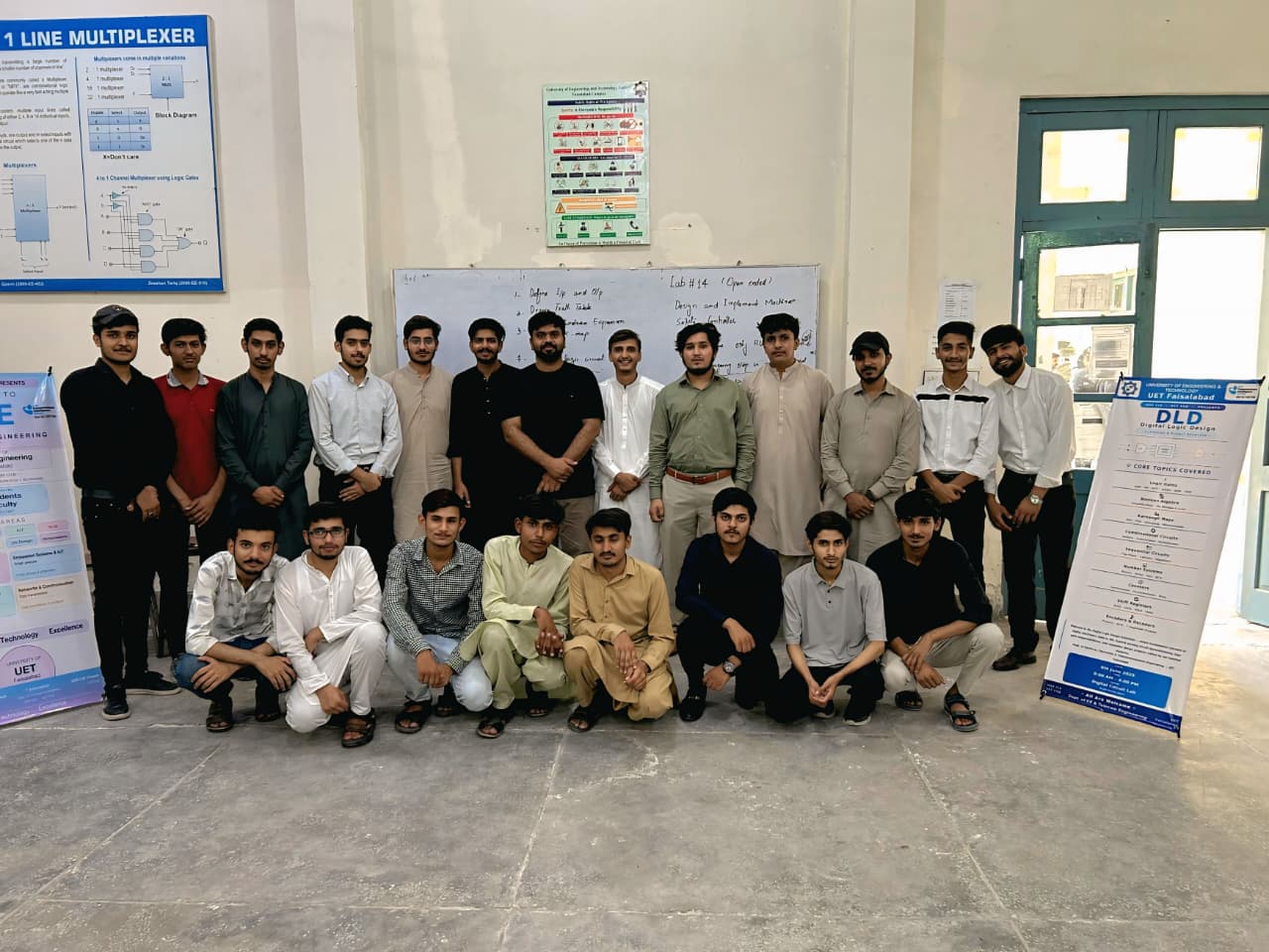
BS Computer Engineering, UET Faisalabad — Second Semester, Spring 2026.